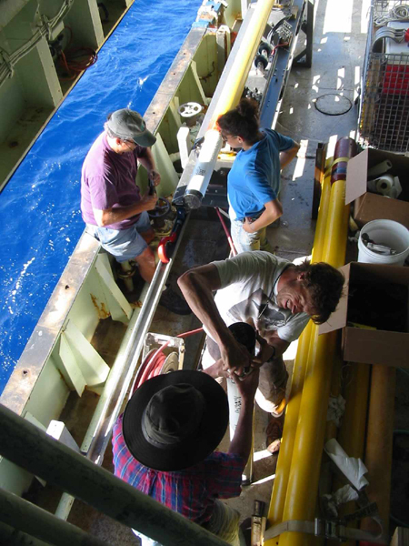
Core Barrel System
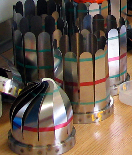
Barrel Array
Composed of sections with three wall thicknesses that share a common inside diameter.
Material cold drawn 4140 [chrome-moly]
Specifications
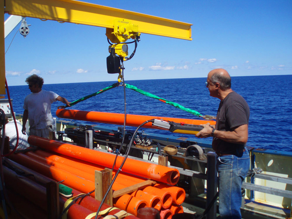
- Heavy wall [1.125”] 7.25” OD x 5” ID 20’ long @ 1500 pounds each. Code = dark red
- Medium wall [.75”] 6.5” OD x 5” ID 10’ long @ 460 pounds each. Code = orange
- Thin wall [.375”] 5.75” OD x 5” ID 10’ long @ 215 pounds each. Code = yellow
Corrosion prevention coatings
- Primer = Whitford Corp. Xylar aluminum filled ceramic (CERMET)
- Topcoat = Whitford Corp. Xylan resin bonded PTFE based dry film lubricant
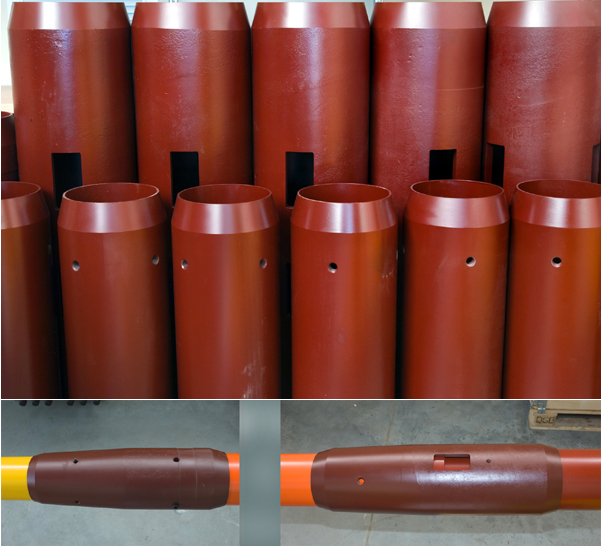
Couplings
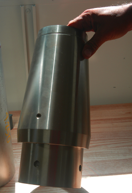
5 types of sleeve-type couplings are employed: 3 ‘straight’ and 2 ‘step-tapered’ to transition the core barrels from one wall thickness to another.
- Material cold drawn 4140 [chrome-moly] - Corrosion prevention coating = xylar/xylan system
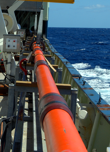
Maximum core barrel length
[current] = 46 meters [150 feet]Barrel handling and assembly
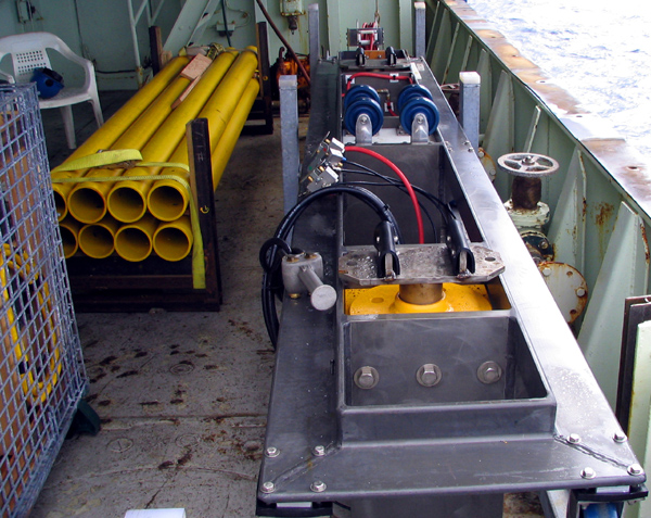
Purpose built pneumatic jib crane delivers barrels to barrel ‘truck’.The pneumatic truck is equipped with a tractor drive to move barrels fore and aft plus air jacks and a vibration system to assist assembly.
Core Liner
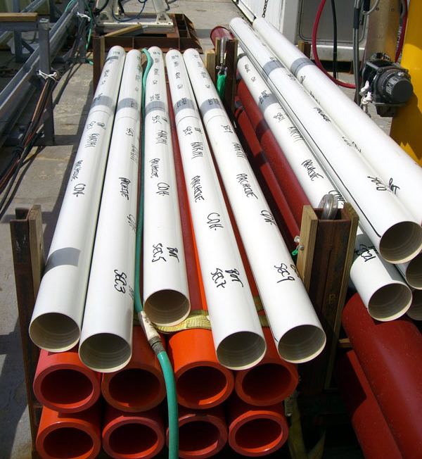
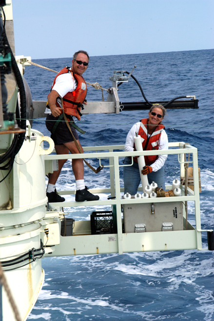
Custom extruded pvc 4.875” od x 4.375” id. Ten foot lengths coupled during assembly via threaded joints at each end.
Core cutter/catcher
Adjustable [via bushings] id core cutters and variable strength core catchers cut and retain the sample.
Material
- catchers - 316L and 17-4PH stainless steel
- cutters - 4140 cdom and 316L
- cutter bushings - AL 6061 and 316 SS
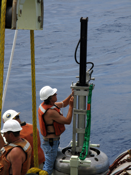
Hydraulic extruder
A powerful hydraulic cylinder pushes 3 inch diameter plastic [HDPE] rods to incrementally extrude the liner at the lower end of the core.
![4L_61892 Racks with three sizes [color coded] of core barrels onboard Knorr](https://www2.whoi.edu/site/longcore/wp-content/uploads/sites/80/2019/07/4L_61892.jpg)
