|
Abstract
The Ice-Ocean Environmental Buoy (IOEB) was developed to acquire and telemeter in near real-time inter-relatable time-series data on atmospheric, oceanographic and ice physics in ice-covered oceans during all seasons. Mechanically, the IOEB consists of an extremely durable surface flotation package and an underwater mooring line of instruments and sensors. The apex contains data loggers for meteorological, ice physics and engineering measurements, microcontroller modules for accumulating the data, and ARGOS platform transmit terminals (PTTs) for broadcasting the data. The ocean sensors include conductivity/temperature recorders, an Acoustic Doppler Current Profiler (ADCP), a dissolved oxygen sensor, a transmissometer and two fluorometers. Furthermore, a suspended particle collector and sediment trap collect biogeochemical samples at the bottom of the 110 m suspended mooring. In April 1992, two IOEBs were successfully deployed at two separate ice camps in the Arctic Ocean with battery power adequate to sustain the systems for over two years.

I. INTRODUCTION
The Arctic is a fascinating area to study, not only because it is one of the last, and least understood, regions of the Earth that has been explored by man, but also because many of its unique properties are so important to global climate change. As a system, it is composed of genuinely interactive elements and processes that cannot be adequately described by confined individual disciplines. Complexity is further increased by the large amplitudes of seasonal variability of the polar environment, which prevents extrapolating knowledge over even relatively short time periods. Consequently, in order to effectively examine processes in this region, what is needed primarily are continuous concurrent observations of the atmosphere, ice and ocean behavior in all seasons. Due to the extreme severity of the Arctic winter, however, manned observation stations are not only costly, but also very dangerous. While there are some particular advantages to the remote sensing of the polar regions by satellites and single-sensored buoys, in situ measurements of a large array of sensors with greater accuracy and intercomparability can be made by unattended automated telemetry stations. Since 1987, we have been developing such a buoy system, called the Ice-Ocean Environmental Buoy (IOEB) which includes extensive atmospheric, ice physics, and oceanographic sensors. In terms of the number of sensors, volume of data, and sophistication of the telemetry system, the IOEB represents an exceptional achievement in the area of ocean remote sensing technology. In particular, emphasis is on the collection of biogenic flux by the buoy mooring system; a technology unprecedented under the ice-covered oceans. Combination of the organic carbon flux with the other critical data will not only aid in understanding the biogeochemical cycles and processes of the Arctic Ocean, but also the associated oceanic interactions with the air and the ice, and their relation to global changes.
II. BACKGROUND
A. Arctic Environmental Drifting Buoy
In 1986 the Arctic Environmental Drifting Buoy (AEDB) was developed to suspend a time-series particle collecting sediment trap underneath the icefloes in the Transpolar Drift, primarily to collect biogeochemical samples in this area of sparse measurements. Furthermore, this mooring was outfitted with an acoustic Doppler current profiler (ADCP) and ice thermistors, to measure respective physical characteristics of the sea and ice. The following year, this prototype of an IOEB was deployed from the F/S Polarstern at the northernmost point, 86 N latitude, obtained during a 61-day cruise [1]. The AEDB was transported over 3,900 km by the Transpolar Drift out from the Nansen Basin, through the Fram Strait, along the East Greenland Current, and was recovered west of Iceland after 255 days in the pack ice and marginal ice zone (MIZ). The AEDB did not have telemetering capability, but each instrument stored the data internally. Upon recovery, significant data were retrieved from a number of instruments on the mooring system. For example, the first independently observed, long-term acoustic Doppler profiler (ADCP) data provided observations on internal waves [2] and diurnal tides [3]. For another example, ice thermistor strings provided data showing the evolution of the thermal profile of sea-ice during the summer in the Nansen Basin, and allowed calculation of the oceanic heat flux in the Fram Strait [4].
Besides the importance of the recovered scientific data, the AEDB demonstrated that it was possible to track and recover a durable suspended mooring system in the Arctic where conventional mooring systems are not always logistically or technically feasible. However, several limitations of the AEDB needed to be addressed to make this system more durable and more valuable to the science. For instance, the 5 foot diameter steel surface package which housed the transmitters was severely dented on all sides by ice pressure north of the Fram Strait and in the East Greenland MIZ. Since this buoy was recoverable, then future systems would need reusable surface packages. Furthermore, because the sediment trap package at the bottom of the mooring parted from the buoy before recovery, a stiffer but stronger steel-based mooring segment would be used to suspend the package instead of elastic nylon rope. However, it is nearly impossible to design any device that can withstand the most enormous ice pressures and environmental characteristics that can occur in the Arctic, and even the most durable system could be destroyed. Consequently, the mooring cables required the addition of conductors to allow transmission of the scientific data from all the instruments, in case of destruction. With these concerns in mind, a Preliminary IOEB (P-IOEB) mechanical package was constructed to test several improvements in the mechanical and electronic design.
B. Preliminary IOEB
One of the major improvements of the P-IOEB over the AEDB was the use of Dupont SurlynR ionomer foam for the outer protective shell of the buoy. This flotation collar surrounds an aluminum chamber housing the surface electronics and is sandwiched between an aluminum top plate and steel bellmouth weldment. The semi-conical collar provides nearly twice the buoyancy required to sustain the 1800 lbs. of surface package and mooring system. To increase abrasion resistance, the foam density used was 10 PCF; double what is commonly used for open ocean floats. The outer skin is further densified by heat and pressure to form an extremely tough outer skin. Furthermore, electrical conductors were added to the 10 m strength cable that was to penetrate through the ice and suspend the underwater mooring system. Only one instrument was attached at the bottom of the ice strengthened E/M cable which comprised the whole mooring system. Below this, a 600 lb anchor was fashioned in the field to simulate a heavier mooring system.
Inside the electronics tube, two Synergetics PTTs transmitted ARGOS data via patch antennas mounted externally on the surface of the top plate. One Onset Computers TattletaleR 3 (TT3) data logger was used to feed data to both PTTs via an RS-232 serial port connection. The data consisted of information from a tensiometer mounted in the bellmouth flange, and seawater conductivity and temperatures from the standard SeaBird SeaCatR at the end of the mooring.
This test package was deployed in sea-ice in the Northwest Passage from the USCGC Polar Sea during mid-September 1990 for 20 hours, while the operation was monitored and engineering measurements were taken. The objectives of the Northwest Passage experiment were to test the strength of a surface buoy and the reliability of the through-ice E/M cable in broken sea ice. The icebreaker was used to induce ice pressure on the float, while observations on the mechanical effects were performed visually, and via ARGOS data transmission. After many successful collisions of the buoy between icefloes, and extended periods of gradual pressure, the buoy was retrieved undamaged from the Canadian waters.
The visual results from this test confirmed the slipperiness of the outer SurlynR foam shell by escaping vertically between 1 m icefloes as they came together around the buoy. Conductivity, temperature, and depth readings were reliably transmitted at all times by the SeaCat'sR serial RS-232 port up the ice-penetrator cable to the TT3. Tension readings from the load cell mounted in-line with the mooring system showed remarkable sensitivity to variations as the surface float bobbed, or was pushed up by icefloes.
The results of the P-IOEB test confirmed that ionomer foam at 10 pcf density could endure Arctic ice conditions and could be reused without major repair a number of times. In addition, although the ice strengthened E/M link performed reliably in marginal ice conditions, later this was changed from an assembly based on wire rope to one which incorporated chain for extra robustness.
III. DESCRIPTION OF IOEB
A. Mechanical Design
Two IOEBs were developed in 1990-91 incorporating the combined improvements over the previous systems, and with additional environmental sensors. The new surface package was constructed using the SurlynR ionomer foam shell, and most importantly, all of the instruments on the IOEB were networked to communicate with independent microcontrollers (MCUs) using an EIA485 standard network configuration in order to provide the telemetry capability. Furthermore, new meteorological and ice sensors were added to the array of scientific sensors.
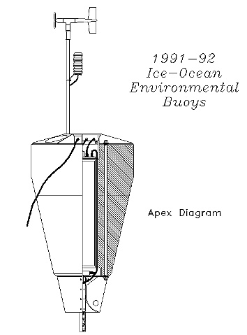
Each IOEB consists of a surface flotation package and a 110 m long mooring system of oceanographic sensors (Fig.1). The surface buoy, or apex, supplies the buoyancy for the suspended instrumentation, and serves as the platform for the satellite transmitters, network MCUs, and meteorological and ice sensors. Deployed through a 1 m hole in an icefloe, the underwater mooring system includes an ADCP, C/T recorders and a complete biosensor package. A 500 lb. anchor serves to keep the mooring taught at the bottom of the system.
The 124 cm diameter apex of the IOEB protectively houses the electronic controller, satellite communication system and battery array for the surface devices, and supplies buoyancy for the drifting mooring. The length of the apex alone is 200 cm. The electronics pressure housing is centrally located in the surface buoy and measures 25 cm I.D. by 125 cm in length. The top end cap accommodates 11 pressure resistant electrical penetrators through which sensor information is conveyed into the tube, and subsequently routed out to the antennas. Inside the electronics tube are dual Synergetics PTTs which provide the uplink signal to the ARGOS satellite. Also inside are dual MCU units, based on TT3 data loggers. These units acquire the data from all the individual instruments on the network, and each supplies the resulting datastream to one of the PTTs. In addition, several mechanical and meteorological sensors, and the data loggers to acquire data from all the air and the ice sensors are also mounted in this tube. The remaining space is occupied by the battery packs to power the surface electronics. This is provided by fused and diode protected packs of Electrochem lithium "DD" oxyhalide batteries assembled in plastic molds. These batteries were chosen for their excellent power density and extreme low temperature characteristics. Nearly 200 cells are required to power the IOEB surface electronics for 3 years at Polar atmospheric temperatures. To create modularity in the design of the electronic network, each PTT, MCU, and data logger was wired to a separate battery supply to provide power independent of the other electronics.
Covering the pressure housing and flotation package, an aluminum top plate protects the cables attached to the penetrators on the pressure housing, provides a platform for mounting the transmitting antennas and meteorological mast assembly, and transmits the mooring line tension through a tie rod assembly. The shape of the flat patch antennas used to convey the transmission from the PTT to the ARGOS satellite allow them to be mounted flush along the top surface of the buoy to prevent damage, and still provide a nearly 180 degree radiation pattern. Furthermore, these antennas may be submerged to a few meters depth without being harmed. In the AEDB, similar oil-filled patch antennas were successfully used, although the 401.650 Mhz ARGOS carrier frequency would shift if oil leaked from the housing. As a result, on the IOEBs, the radiating and reflecting surfaces are now encased in a hard epoxy mold, with a two-wire coaxial pressure resistant cable protruding out from the underside.
Located at the bottom of the surface buoy, a galvanized steel bell-mouth flange reduces the strain on the armored conducting cable which attaches to the mooring system. The E/M link connecting the surface buoy to the E/M mooring cable consists of 3/8" trawler chain with three conductor jacketed cable terminated with steel clevises, and polyurethane potted to form a semi-rigid, water-tight link 6.35 cm in diameter and over 7 m long. The other underwater mooring segments are constructed from jacketed steel armored three-conductor cables. Each end of the cable is fitted with an E/M termination and a unique underwater T-splice connector for electrical access to the EIA485 network. These cable assemblies have a breaking strength of 4700 kg. Between terminations, stainless steel cages contain most of the IOEB instruments; positioning them in-line with the mooring system.
B. Sensors and Instruments
The scientific sensors on the IOEB can be divided into three main categories: meteorological sensors, ice sensors, and ocean sensors. Simultaneously, data is acquired by all the sensors throughout the lifetime of the buoy. While individual groups of sensors are included with specific scientific objectives in mind, intercomparison between sensors from different fields may lead to the most innovative results. All sensors that are located in the air, in the ice, or in the surface float are rated to operate to temperatures at least as low -40 C, in order to function during the severe cold Arctic winter. Underwater instruments are rated to at least -5 C operation.
The IOEB meteorological sensors consist of a Paroscientific DigiquartzR barometric pressure sensor mounted inside of the electronics tube, and ported to the surface atmosphere through a labyrinth water trap, and a 6 foot long aluminum mast protruding above the top plate and supporting a R.M. Young air temperature sensor with radiation shield, and a R.M. Young wind monitor. Furthermore, the meteorological data logger obtains a small amount of mechanical information: an Aanderaa magnetic compass and Spectron electrolytic X/Y tilt sensor detect the rotation and incline of the top package, while a Metrox load cell measures strain at the mooring cable junction.
Nearby the apex are installed ice sensors which are interrogated by a Campbell ice data logger inside the electronics housing. Two ice thermistor chains, comprising a total of 33 thermistors profile temperatures from the ice surface down into the surface seawater, similar to the AEDB. Improving on the previous buoy, however, the IOEB obtains a more precise ice thickness measurement from a Simrad echo sounder module pointed upward from a mount situated below the icefloe, and Geokon stress sensors measure internal ice stress in two direction at three depths in the icefloe.
In the seawater below the icefloe, oceanic measurements are made by an ADCP, an electromagnetic current meter, 3 C/T recorders, a dissolved oxygen sensor, 2 fluorometers, a transmissometer, a time-series microfiltering suspended particle collector, and a time-series sediment trap.
Two units on the mooring line measure currents. The first is an RD Instruments 150 kHz ADCP which collects ocean current data in a profile underneath the sea-ice. Using the Doppler principle, the ADCP determines currents in a series of depth bins below its sensor faces, and collects temperature, heading and tilt information at the device's depth. The ADCP produces (and internally records) the largest amount of data each transmission cycle, compared to the other instruments. As a result, a data processing module (DPM) is required to interface between the ADCP and the buoy telemetry system by processing and reducing the information so that a representative subset of the data can be broadcast via the ARGOS system. The DPM was developed by Pleuddemann et al. [5] primarily for implementation on the IOEB. Due to the maximum allowable data rate through ARGOS, the ADCP data is reduced by about a factor of 170 by the IOEB DPMs.
The other current measuring unit is an InterOceans S4R current meter which determines current electromagnetically. In order to communicate with the surface electronics, a separate underwater data buffer module is required to interface between the units. Outfitting the IOEB S4sR with a temperature probe and an inductive conductivity sensor also provides a deep watermass data point along the IOEB mooring line.
SeaBird SeaCatR conductivity and temperature recorders are used at 3 locations along the mooring line to provide points above, below, and in the holocline. One unit is outfitted with a dissolved oxygen probe and a fluorometer specifically to detect primary productivity. SeaBird Electronics cooperated extensively by modifying both the firmware and communications hardware to converse with the data acquisition electronics in the surface buoy, using the appropriate protocol. A second Sea Tech fluorometer, paired with a Sea Tech transmissometer, have a separate TT485 data logger for acquiring data and communicating with the surface electronics.
McLane Research water transfer systems with 18 NucleoporeR filters, are deployed at different locations on the separate IOEB mooring lines. One water transfer system is independently located at a shallow depth, while at the very bottom of the conducting cable, the other pumping system is paired with a McLane Research 21-sample sediment trap, providing information on both suspended and falling particles at that depth.
Except for the suspended particle collector and sediment trap, most of the information from all of the above instruments are digitized electronically, collected by each MCU, and transmitted via the ARGOS satellite back to the laboratory in near-real time. The buoy systems are intended to be recovered and most instruments record their complete datasets internally, but only the particle collectors require retrieval so that laboratory analysis can be performed on the acquired samples upon completion of each buoy's journey.
C. Electronic Architecture
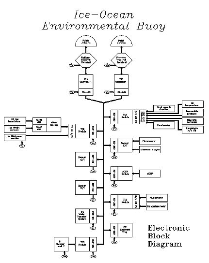
The IOEB uses the IEEE EIA485 standard [6] for network communications from individual instruments to two MCUs, which in turn transfer data to PTTs for real-time satellite transmission. The EIA485 standard specifies the electrical characteristics of generators and receivers for the interchange of binary signals in multipoint interconnection of digital equipment. Implementing this standard means that multiple instruments may be networked using only two individual conducting cables. This is mechanically advantageous because it eliminates the bulkiness of multi-cable assemblies that would be required using other dedicated single-point standards. On the other hand, complexity in the system is increased, since care must be taken to ensure that only one driver is active at a time, or meaningless overlapping communications will occur. By sequential addressing, each controller allows only one of the data buffers to be active on the network at any time. Each individual data logger, data buffer, controller, and transmitter module is provided with separate battery power supply to ensure isolation from faults passing between units.

The Serial ASCII Instrumentation Loop (SAIL) data communications standard [7] was adapted to define the software protocol on the instrument network. On the IOEBs, the network MCUs begin each sequence by sending an attention character ("#") over the network, which wakens all of the instruments on the mooring system. Each of the devices is individually interrogated serially at 9600 baud, by sending the attention character first, followed by the unique two character address and the character "R". When addressed, an instrument responds by repeating its address followed by ASCII hexadecimal data, and the message terminator character ETX.
Because more than 256 bits of data is being acquired by the IOEB sensors every measurement interval, a complicated transmission scheme is used to compress all of the information for ARGOS broadcasting (Fig.2). According to the particular sequence, each MCU interrogates a subset of the IOEB instrumentation, compiles the data and then passes it to a PTT via an auxiliary UART circuit. Then, after hibernating in micropower mode for approximately 57.5 minutes, the MCU implements the next sequence and repeats the process. There are a total of six sequences that each MCU utilizes, and for simplicity in the modular design, each MCU exclusively controls the flow of all sensor data to only one PTT.
The first three bits in every IOEB transmission indicate the sequence number that is being broadcast. Since each sequence has its data broadcast for a period of just under one hour, after nearly six hours, all of the sequences have had all of their data transmitted, and this process repeats from the beginning. According to this scheme, instrument data that is acquired infrequently may only be broadcast once during the six sequences, while the more frequent data may be updated every other sequence. The same sequence formats are transmitted by each PTT/MCU pair, only during operation their timing is offset by 3 and a half hours to maximize the data throughput of the combined units. In effect, when both pairs are operating properly, the frequency of the data transmission is doubled, which allows some of the broadcast sensor data to be updated nearly every hour.
During operation, each IOEB transmits 512 bits of new sensor information every 60 minutes via ARGOS. This is equivalent to a throughput of 12k bits/day of new data per buoy. Currently this data is being collected and processed daily in both the United States and Japan.
IV. FIELD OPERATION AND PRELIMINARY RESULTS
Two IOEB systems were deployed in April 1992 from separate air-supported ice camps. Simultaneously, a reduced version of the IOEB (based on the P-IOEB), was deployed by the Scott Polar Research Institute in the Weddell Sea, Antarctica, but that system will not be included here. One IOEB was deployed on April 15, 1992 at 88 N, 57 E, and the second at 73 N, 142 W, nine days later. The first was situated in the center of the Transpolar Driftstream ice current, from the northernmost ice camp, Camp Crystal of the Arctic Regional Environmental Activity, 1992 (AREA 92) of the Space and Naval Warfare Command. The other was located along the edge of the Beaufort (Canadian) Gyre current, being installed from the ONR maintained Lead Experiment (LEADEX) Camp, approximately 150 miles north of Alaska. In terms of efficiency and flexibility, these ice camp expeditions proved to be better platforms for deploying the intricate IOEB systems than conventional icebreakers. Fig.3 indicates the deployment location and drifts of each buoy for the first year.
Fig.3. Deployment locations and first year drift tracks of 1992 IOEBs.
Sixteen months after deployment, the Beaufort IOEB is located at approximately 78 N 158 W and is proceeding north. The ice sensors onboard this IOEB were lost when the icefloe cracked and the package was temporarily dropped into a small lead on July 9, 1992. The C/T recorders stopped functioning after only 2 months; presumably because of power problems. At present most of the meteorological sensors, ADCP, fluorometer, and transmissometer are still transmitting credible data. The sediment trap and suspended particle collectors should be functioning as well; however, the real status of the long awaited biogeochemical samples will not be known until the buoy is recovered. We expect the Beaufort IOEB to be active for another two years, based on power consumption calculations.
The IOEB deployed at Camp Crystal stopped transmitting on July 9, 1992 at approximately 85 N 37 E, after having transmitted intermittently since May. We suspect PTT malfunction to have caused this failure. However, most data gathered by this IOEB are being recorded in memory, so if this system is able to be recovered, we should be able to retrieve this information.
Currently we are still acquiring and interpreting the near real-time data from the Beaufort IOEB. The full results will be published elsewhere.
V. SUMMARY
In general, the concept of an automated polar telemetering station with many atmospheric, ice profiling and oceanographic sensors is feasible for gathering fundamental data to aid in the understanding of long-term environmental alterations in the Arctic Basin. In particular, the use of a SurlynR ionomer foam rather than a conventional steel surface buoyancy package promotes survivability, as well as reusability of the buoy package. Furthermore, applying the EIA485 standard to two-conductor multipoint mooring cable usage enables the telemetry of most of the data from the scientific sensors. The related development of the DPM for the compression of ADCP data demonstrates how a representative subset of a massive volume of data can be compressed to be easily telemetered using via ARGOS. By incorporating a modular design, the number and type of sensors which are employed on the IOEB may vary as required, but in order to succeed as an automated station, each system should include sensors in the air, ice and ocean to assist interdisciplinary study.
ACKNOWLEDGMENTS
We thank K. Doherty for designing the mechanical aspects of the IOEB and J. Kemp for directing the deployment of both IOEBs. H. Bosworth ably assisted the deployment by operation at Camp Crystal. We thank the USCGC Polar Sea for providing the platform for the P-IOEB experiment. This program has been supported by the Office of Naval Research (Contract No. N00014-89-J-1288) and the Japan Marine Science and Technology Center.