Grid
Geographic Domain
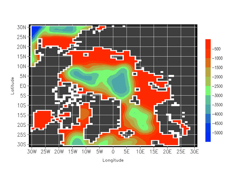
The AOMIP Grid is defined over a geographic domain that includes the Arctic Ocean, the Bering Strait, the Canadian Arctic Archipelago, the Fram Strait and the Greenland, Iceland, and Norwegian Seas.
Horizontal Grid
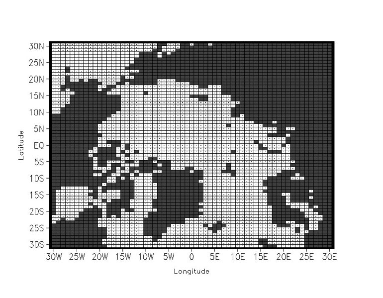
The horizontal coordinates are spherical and are rotated by the Euler Angles (-30, -90, 0) with respect to the true, geographical coordinates of the earth. This places the model north pole along the real earth’s equator at a longitude of 30 ºW. The AOMIP-Grid horizontal spacing is 0.5º in latitude and longitude. The AOMIP Grid extends to ± 30 º N and ± 30 º E, and fully covers the geographic domain described above. All AOMIP models compute their basic prognostic quantities on staggered horizontal grids. The AOMIP grid, however, requires that all prognostic quantities be reported at collocated points. This arrangement is often referred to as the A-Grid (Arakawa, 1966).
Vertical Grid
The AOMIP ocean models represent a variety of different vertical coordinate schemes, namely, height, sigma, and isopycnic. This raises the question whether to convert all model output to a standard vertical coordinate system, or to have each model output represented in its native-vertical coordinate system. We have decided to convert all model output to height coordinates. The AOMIP-Grid vertical spacing is defined at 30 depth levels.
| Index | Depth (m) |
|---|---|
| 1 | 0 |
| 2 | 5 |
| 3 | 10 |
| 4 | 15 |
| 5 | 20 |
| 6 | 25 |
| 7 | 30 |
| 8 | 40 |
| 9 | 50 |
| 10 | 75 |
| 11 | 100 |
| 12 | 125 |
| 13 | 150 |
| 14 | 200 |
| 15 | 250 |
| 16 | 300 |
| 17 | 350 |
| 18 | 400 |
| 19 | 500 |
| 20 | 600 |
| 21 | 750 |
| 22 | 1000 |
| 23 | 1250 |
| 24 | 1500 |
| 25 | 2000 |
| 26 | 2500 |
| 27 | 3000 |
| 28 | 3500 |
| 29 | 4000 |
| 30 | 5000 |
Euler Angles
In AOMIP there exists three distinct coordinate systems: (i) the true, geographic coordinates of the earth, (ii) the native (possibly rotated) coordinates of an AOMIP model, and, (iii) the AOMIP-grid (rotated) coordinates. Depending on the particular AOMIP model, some of these coordinates may be coincidental, but in general this will not be so. From the practical standpoint of getting AOMIP native-grid model output onto the common AOMIP grid, we describe an algorithm to remap scalar and vector fields from the one coordinate system to the other. The algorithm is a combination of rotations and interpolations. The interpolations are not discussed.
As a starting point we use a theorem by Euler that guarantees the existence of a rotation sequence that will properly relate two independent coordinate frames (i.e., a native-grid coordinate system and the AOMIP-grid coordinate system) (Kuipers, 1999):
Any two independent orthonormal coordinate frames can be related by a sequence of rotations (not more than three) about coordinate axes, where no two successive rotations may be about the same axis.
This means that we can find a sequence of rotations about successive coordinate axes that will rotate any model native-grid into the AOMIP-grid. The maximum number of rotations is three, and in practice two or even one rotation may suffice. The angle of rotation about a coordinate axes is called an Euler Angle. A sequence of such rotations is called an Euler-Angle Sequence. The sequential order of the axes about which rotations are performed matters greatly.
The restriction that successive axes of rotation be distinct permits exactly twelve Euler-Angle Sequences (for a three-dimensional space). That is to say any model native-grid can be brought to the AOMIP-grid in any of a dozen ways. For the moment, let us contemplate rotating in three-dimensional cartesian coordinates, that is reference frames made up of orthonormal coordinate axes X, Y, and Z. Native model output is generally in spherical coordinates, and not cartesian, and this point of detail and is addressed below.
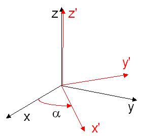
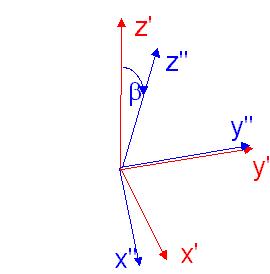
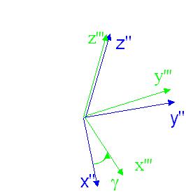
To achieve an Euler Angle Sequence, we need to know what sequence of axes we are going to rotate about and what magnitude of angle we will rotate for each of the three axes. These angle have nomenclature of alpha, beta, and gamma, for the first, second, and third rotations, respectively. Of all the possible rotation sequences, we pick the sequence known as "ZYZ". This means we rotate about the initial Z axis by angle alpha, then the new rotated Y axis by the angle beta, and then finally the new rotated Z axis by the angle gamma.
We provide more explicit detail describing how we move from a model native-grid (we call that reference frame S) to the AOMIP-grid (we call that reference frame S'''), by a sequence of rotations through the intermediate reference frames S' and S''. Starting in frame S, with cartesian axes X,Y, and Z, we rotate
Each rotation may be described by a matrix operator. The net rotation achieved is the product of three such matrix operators, giving a single rotation matrix, the Euler matrix.
The inverse of this matrix can be used to reverse the transformation, that is, to go from the AOMIP-Grid to the native-grid.
The above has concentrated on the concept of coordinate rotation (i.e., changing the orientation of a given coordinate system, e.g., cartesian). Mention is now made of the concept of coordinate transformation (i.e., changing from one coordinate system to another, e.g., cartesian to spherical). Since the surface of the earth is spherical then spherical coordinates are an obvious choice for representing position in an ocean model. However, as the Euler matrix, as given above, works on cartesian coordinates, it is necessary to first transform native-grid model ouput from its spherical coordinates to cartesian coordinates. Details of cartesian to spherical coordinate transformation are given elsewhere. After coordinate rotation via the Euler matrix, it is necessary to perform the inverse transformation from cartesian coordinates back to spherical. Only in that final step will the native-grid model output be correctly placed on the AOMIP-grid.
Fortran-90 code fragments are provided to assist with the coordinate transformations from spherical to cartesian, the coordinate rotations by Euler Angles, and the inverse of these operations.
Vector Rotation
Up to this point the discussion has focused on how to transform and rotate a scalar field, but not a vector field, such as ocean currents. A vector field is processed in a two-step procedure. First, each of the vector components (i.e., which are just scalar quantities) are transformed and rotated just as is any other scalar field. This procedure results in a vector-field being transformed and rotated from a model native-grid to the AOMIP-grid with the correct magnitude but with the wrong orientation. The orientation is corrected by taking a unit vector and processing it through the Euler Angle Sequence. A Fortran-90 code fragment is provided to assist with vector rotation.
